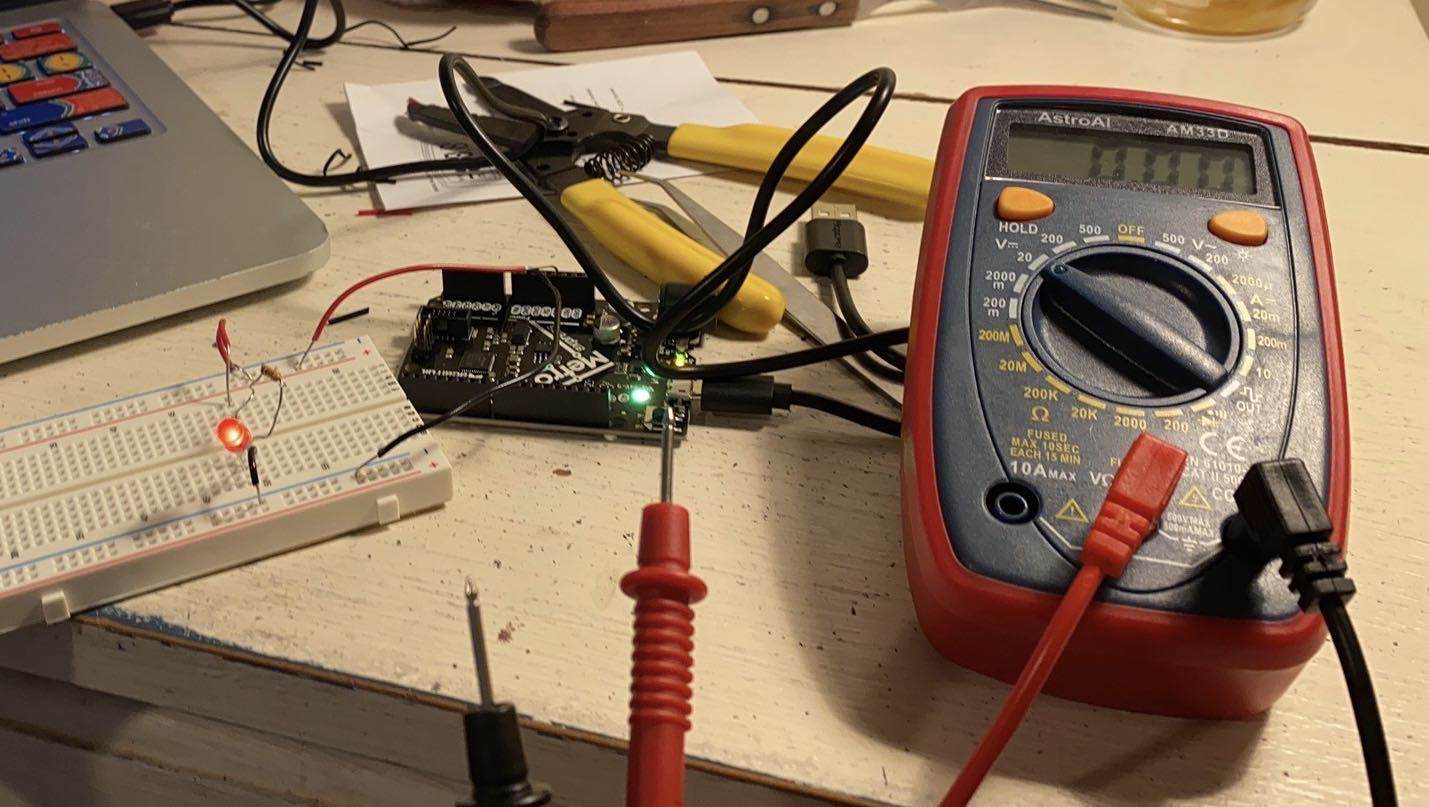
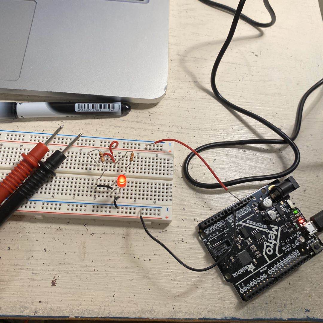
The goal of this class was to leanr about teh basics of circuit and get familiar with settiing up circuits on a breadboard. We started with learning about current and voltage. Current flows through a circuit, and votage describes the energy of teh charges at a particular place in the circuit. The first exercise was to set up a basic circuit taht consists of a resistor and a LED. A microcontroller provides a 3.3v voltage in this particular case. The longer leg of teh LED goes to the anode(positive side) of the circuit. I was able to better understand the way a breadboard works, allowing current to flow under each row and colume. To enclose my circuit, I needed to use wires to make connections across rows and columns. This pictures shows the LED being lighted up.
A multimeter was used to measure the voltage drop, the loss in electric potential. With a multimeter, I proved that the voltage drop around each component in the circuit adds up to the total voltage around the power supply. I used multimeter later in the class for debugging my circuit as well. I used the probes of the multimeter and attached them to the ends of each segment of the wires, in order to detect the discconneted spot according to the beeping sound.
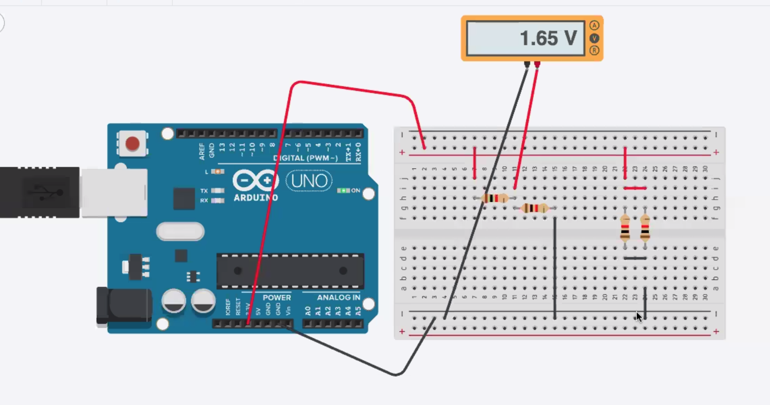
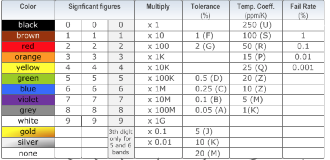
I then silulated two simple circuit on Tinkercad. I used Tinkercad to complete simulations of different types of circuit. Tinkercad is a great tool for foreseeing the circuit before building a physical one. I learnt about the color coding rules for resistors, on which different colored strips represent the number of significant figures and teh multiplier.
I also learnt how to use Arbuino to communicate with the Metro MO microcontroller. By importing a example program, I successfully made connection between my laptop and the microcontroller. As shown in the video below, the red LED on the microcontroller is "blinking".
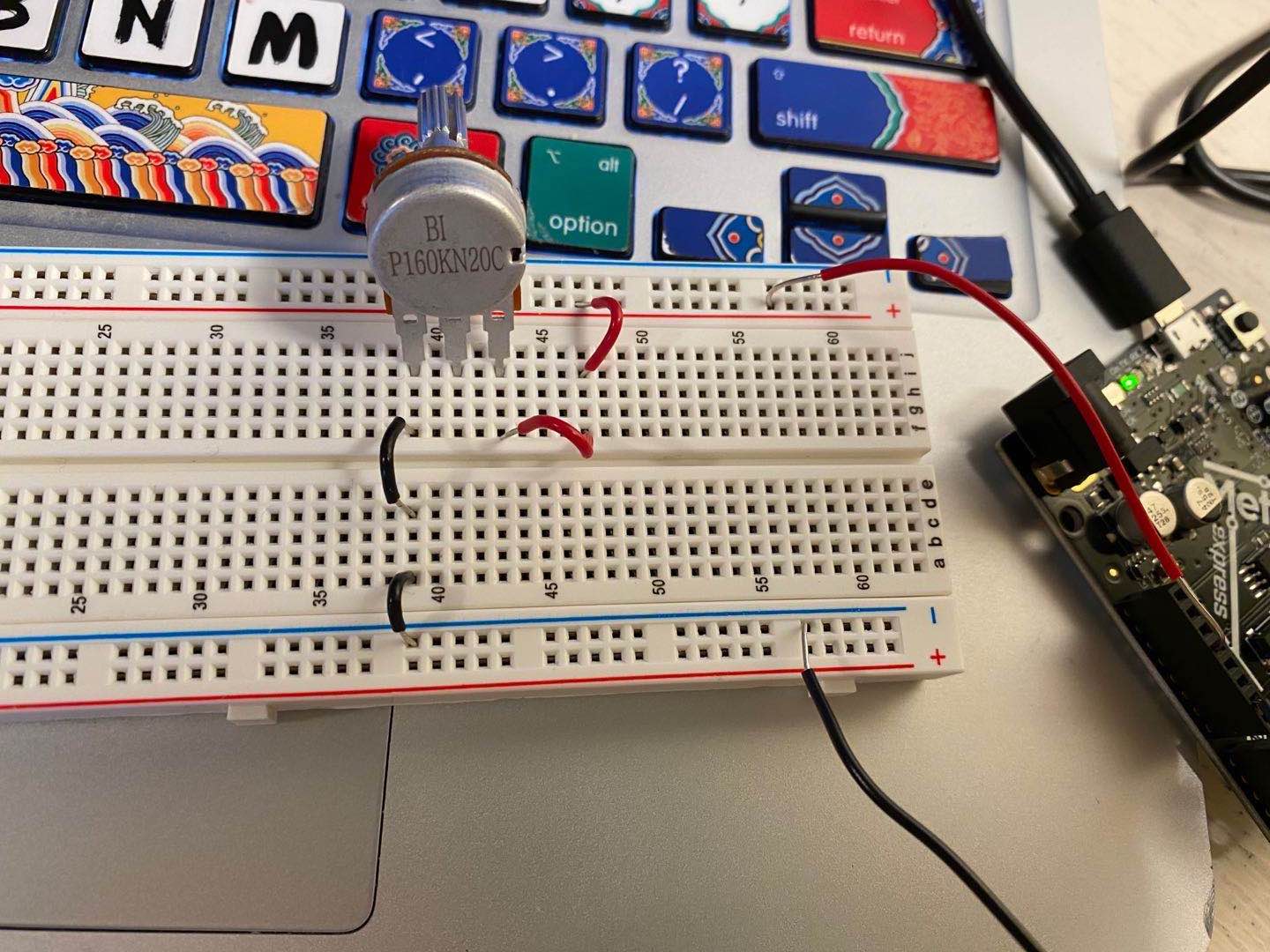
During the lab, I learnt to measure the varying voltage drop around a potentiometer. With the Microcontroller in (ADC). I had a hard time setting up my circuit, with the measurement fluctuating between 0.01v and 0.02v. The multimeter came handy in this case to help locate the problem in my circuit.
After class, I explored on two different ways of connecting two resistors, in series and in parallel, as what I did on Tinkcad early. Two resistors connected in series can be used as a voltage divider, because there is a voltage drop after each resistor. According to Ohm's Law (I=V/R), I was able to calculate the current in this circuit with measurements taken by the multimeter. As for the parallel circuit, I used the same method to measure voltage drop and calculate current. I found that the voltage drop around one of the resistors equals to the one around the power supplier. I also found that the more identical parallel resistors I added, the less total resistance this structure had.
Considering that my final project may contain two or more electric conponents, I decided to experiment on the efficiency of parallel circuit and series sircuit. Because in a parallel structure, the voltage around each branch are the same as the total voltage, it works better in providing enough energy for different parts of my design. Also, when I tried to cut off one branch from the parallel ciruit, the rest were still functioning. When I did the same thing to the one in series, the entire circuit was broken. This finding also contributes to why I prefer a parallel circuit in my final project.
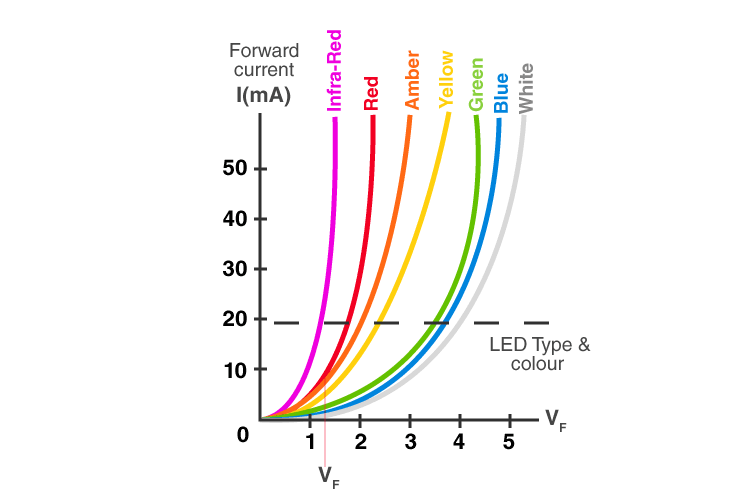
The power inside different colors of LED is another thing I explore after class. I tried to substitute the red LED from my basic circuit with LEDs in other color. I found that the voltage drop around them indeed changed (unfortunately, as we tried duirng lab time, Tinkercad wasn't able to show this). I then looked at the I-V curve of resistors and LEDs. The slope of the graph shows the resistance (Ohm's Law) and the area under show the power (P=VI) The I-V curve for resistors has a constant slope(1/R), meaning a constant resistance. The voltage of LEDs shows a very small change acccording to the graph.
This graph visually shows the behaviors of LEDs with different colors.